
Hollow Shaft Planetary Gearbox: Design and Selection Guide
A hollow shaft planetary gearbox combines planetary speed reduction with an output bore that can receive a machine shaft, pass services through the rotating axis, or simplify a compact transmission layout. The hollow output is useful, but it changes how torque is transferred and how the load must be supported. Bore size alone is therefore not enough to select the gearbox.
Before requesting a model, define what must pass through the center, how the driven shaft will be locked, which external loads reach the gearbox, and whether the application needs only torque transmission or a complete load-supporting rotary platform. Those answers often determine whether a hollow-output reducer, a conventional planetary gearbox, or a hollow rotary table is the correct component.
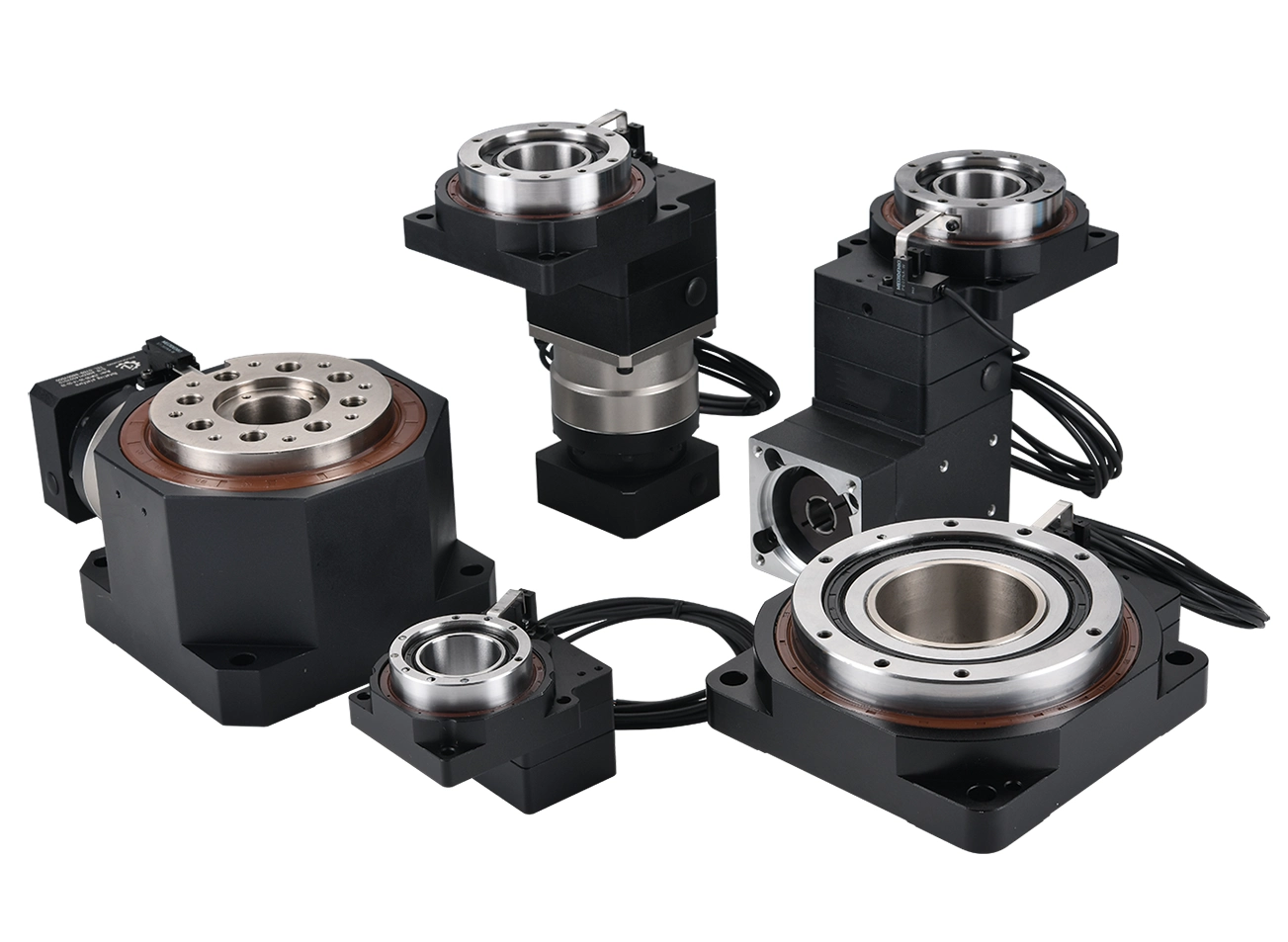
What Is a Hollow Shaft Planetary Gearbox?
In this article, “hollow shaft” refers to the gearbox output: the rotating output member has a central bore instead of a conventional projecting solid shaft. The machine shaft may pass into or through that bore, depending on the design. This is different from the hollow input adapter found on many servo gearboxes. A motor-side clamping hub may look hollow before assembly, but it does not make the reducer a hollow-output gearbox.
The planetary stages still perform the familiar transmission task: they reduce motor speed, multiply usable torque and share load through several planet gears. What changes is the last mechanical interface. The output torque must move from the planet carrier into a hollow hub and then into the driven shaft through a key, spline, shrink disc, clamping element or another engineered connection.
That additional interface is the reason a hollow shaft gear reducer cannot be chosen from reduction ratio and nominal torque alone. The bore weakens the available cross-section compared with some solid outputs, while the connection method introduces its own contact pressure, fit and assembly requirements. A sound design treats the reducer, driven shaft and locking system as one torque-transmission assembly.
Why Designers Choose a Hollow Output
Direct installation on the driven shaft
A machine shaft can enter the output bore without a separate projecting gearbox shaft and external coupling. When the surrounding structure is designed for it, this can shorten the drive train and remove one alignment interface. It may also make replacement easier because the reducer is located concentrically around the shaft it drives.
Routing through the rotation axis
Some machines need electrical cables, pneumatic tubes, vacuum lines, sensor wiring or a stationary service pipe to pass through the center of rotation. A through-bore can provide a cleaner route than an external cable loop. However, the required clear aperture must be confirmed after allowing for sleeves, connectors, bend radius, strain relief and assembly clearance. A cable bundle that measures 25 mm across does not automatically fit a 25 mm bore in service.
Reducing axial packaging length
Placing the gearbox around the driven shaft can reduce the space occupied by a coupling and shaft extension. This is useful in compact automation modules, rotary fixtures and machine frames where axial length is tightly controlled. It does not always reduce total machine size: a shrink disc, torque arm, bearing housing or service-access space may still be needed.
Creating a clean coaxial torque path
For a same-axis arrangement, the hollow output can keep the motor, gearbox and driven member concentrically organized. That can simplify the layout, but it does not remove the need for accurate fits. The gearbox pilot, shaft fit, locking element and external bearing centerline must still be controlled.
How the Hollow Output Connects to the Machine Shaft
The output connection decides how torque moves into the driven shaft. It also affects backlash, service access, shaft machining and cost. The following methods are not interchangeable.
Keyed bore
A key and keyway provide a familiar, economical connection. They are practical where small angular clearance is acceptable and the direction of torque does not reverse aggressively. For precision servo positioning, fit tolerance and keyway clearance require careful review because lost motion at the shaft connection can cancel the benefit of a low-backlash gearbox.
Shrink disc or friction-locking assembly
A shrink disc clamps the hollow hub onto the driven shaft through friction. It can transmit torque without a keyway and can provide a low-clearance connection when correctly sized and assembled. The contact surfaces, shaft tolerance, material strength, tightening sequence and available installation space must match the locking-element specification.
Splined hollow output
Splines distribute torque over several teeth and can suit higher loads or repeatable assembly. They require compatible shaft geometry and tighter manufacturing control. Depending on the fit, splines may allow axial movement or may be designed as a fixed connection. Backlash at the spline must be included in the system accuracy budget.
Clamping hub or custom coupling interface
Compact servo mechanisms may use a split clamp, tapered element or application-specific hub. This approach can solve a difficult packaging problem, but the interface must be reviewed for torque capacity, balance, concentricity and access to fasteners. A custom connection should be defined by a drawing rather than a verbal description.
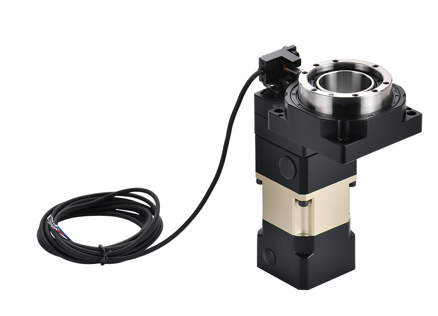
Seven Checks Before Selecting a Hollow Shaft Planetary Gearbox
1. Define the usable bore—not only the nominal bore
Specify the minimum clear diameter required through the complete assembly. Check whether the bore is open from end to end and whether internal shoulders, retaining rings, sleeves or clamping components reduce the usable passage. If connectors must pass through during assembly, size the bore for the connector rather than only the cable.
2. Separate transmitted torque from supported load
The reducer may transmit torque without being intended to support the full weight, overturning moment or belt pull of the machine. Identify radial load, axial thrust, overhung load and moment load separately. If an external bearing set supports the driven shaft, show its position relative to the gearbox. This prevents the gearbox output bearings from receiving loads that belong in the machine structure.
3. Use continuous and peak torque
Continuous running torque determines thermal duty, while acceleration, emergency stops, product jams and rapid reversal create peak torque. Provide both values and the motion cycle. The output locking method must also withstand the same peak events; selecting a gearbox with adequate torque but an undersized shrink disc does not create a safe drive.
4. Confirm the ratio against motor speed and machine speed
The required ratio should place the motor in a useful operating range while producing the necessary output speed. Very high ratios may require additional stages, which affect length, efficiency, inertia and heat. This article does not repeat the full ratio calculation because PlanetDrivePro already provides a dedicated planetary gearbox ratio guide.
5. Budget backlash across every interface
Catalog gearbox backlash is only one contributor to output error. Clearance in a keyway, spline, clamp, machine bearing, fixture and load can add lost motion. In a reversing servo axis, the complete mechanical chain should meet the positioning requirement. Do not specify an expensive precision grade while leaving an uncontrolled output connection beside it.
6. Check shaft fit, wall thickness and material
The driven shaft diameter, tolerance, surface condition and material affect the connection. A larger bore is not automatically better because it reduces the material surrounding the opening and may increase gearbox frame size. The shaft and hollow hub must be checked together for contact pressure, torsional stress and assembly method. Detailed gear load calculations may refer to established engineering methods such as the ISO 6336 series, but final sizing still depends on the actual reducer and interface design.
7. Leave room to install and remove it
A compact drawing can become impossible to assemble if there is no access for clamp screws, retaining hardware or a puller. Confirm the direction from which the gearbox slides onto the shaft, the available tool space and how the unit will be removed after years of service. Include the motor connector and cable bend radius in the same layout review.
Where a Hollow Shaft Speed Reducer Fits Best
A hollow shaft speed reducer is most useful when the output bore solves a real integration problem. Suitable examples include a compact rotary mechanism built around an independently supported shaft, a cable-through automation axis, a driven roller with limited axial space, or a fixture where the gearbox must surround an existing shaft.
It is less suitable when the reducer is expected to act as the machine’s complete turntable bearing, support a large fixture directly, or carry a high overturning moment without a separate bearing structure. In those cases, a hollow rotary table or a purpose-designed output bearing assembly may be more appropriate.
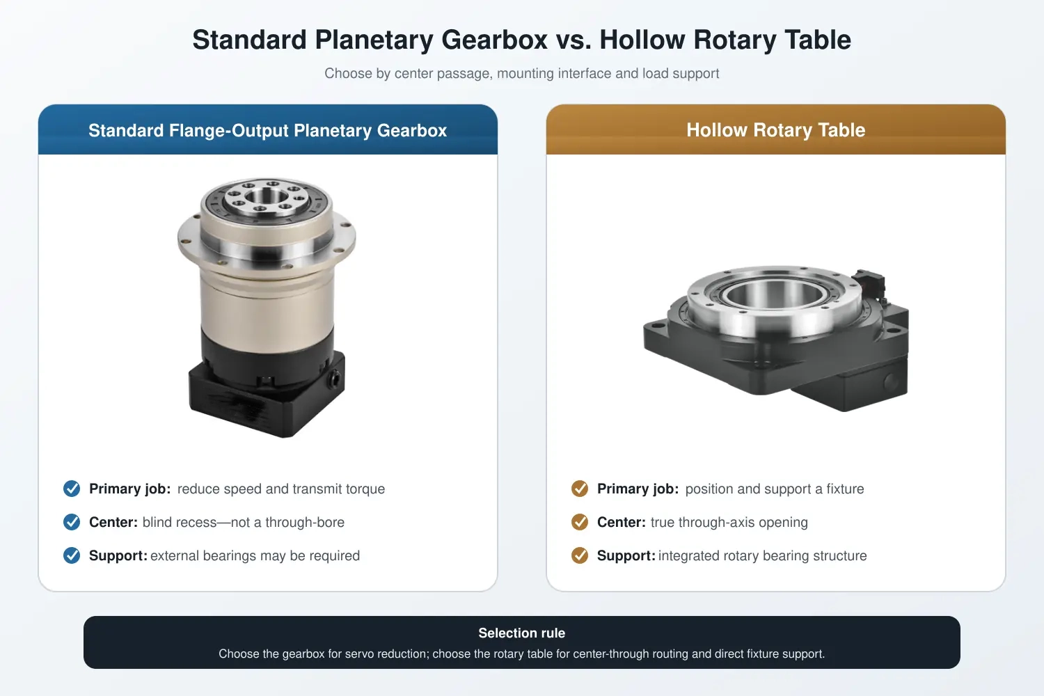
Hollow Shaft Planetary Gearbox vs Hollow Rotary Table
These products may both have a central opening, but they solve different mechanical problems. Confusing them is a common source of undersized bearings and unnecessary custom work.
| Decision point | Hollow shaft planetary gearbox | Hollow rotary table |
|---|---|---|
| Primary job | Reduce speed and transmit torque through a hollow output | Provide reduced rotary motion plus a load-mounting platform |
| Load support | May require external shaft bearings or separate structural support | Designed to support a directly mounted rotating fixture within stated limits |
| Output interface | Driven shaft enters a keyed, splined or clamped bore | Fixture bolts to a rotating flange or table surface |
| Typical reason to choose | Direct shaft connection, coaxial layout or through-axis routing | Large central aperture, direct fixture mounting and rotary positioning |
| Critical checks | Bore fit, locking method, shaft support and transmitted torque | Axial/radial load, moment load, aperture, accuracy and fixture size |
If the machine already has a correctly supported driven shaft and mainly needs reduction, a hollow-output gearbox may be the cleaner solution. If the component must carry a fixture, provide a large clear aperture and deliver indexed rotary positioning, review the hollow rotary table instead.
Common Specification Mistakes
- Calling the motor input hub a hollow output: confirm which side of the reducer contains the through-bore.
- Providing only bore diameter: include tolerance, usable depth, shaft material and locking method.
- Ignoring external bearing locations: the distance between the load and support bearings controls moment and shaft deflection.
- Assuming the gearbox carries the fixture: confirm allowable radial, axial and moment loads instead of treating the housing as a turntable.
- Checking rated torque but not reversal: peak torque and repeated direction changes affect the reducer and shaft connection.
- Using “zero backlash” without a test condition: gearbox backlash and connection clearance must be evaluated separately.
- Leaving assembly until the end: a design that fits in CAD may still lack space for clamping and removal tools.
What to Send for a Hollow Shaft Planetary Gearbox Review
Because output geometry is application-specific, a useful request contains more than motor power and ratio. Send the following information:
- Machine function and a layout drawing
- Servo or stepper motor manufacturer and full model number
- Motor speed and required output speed
- Required reduction ratio
- Continuous, acceleration and emergency peak torque
- Driven shaft diameter, tolerance, material and available engagement length
- Minimum clear through-bore requirement
- Preferred keyed, splined or friction-locking connection
- Radial load, axial load, overturning moment and load application distance
- External bearing arrangement
- Backlash or positioning requirement
- Duty cycle, mounting direction and operating environment
- Prototype and expected production quantities
Dongguan Zhuochuang Precision Machinery Co., Ltd. manufactures precision planetary gearboxes and hollow rotary tables for servo-driven automation. For a hollow-output requirement, the team can first review whether an available planetary gearbox configuration, a customized interface, or a hollow rotary table is the more appropriate route. This avoids presenting a standard gearbox as suitable before the shaft, load and mounting conditions are known.
For standard inline and right-angle configurations, review the precision planetary gearbox . For a project-specific evaluation, send the motor model, shaft drawing and working conditions to Zhuochuang.
FAQ About Hollow Shaft Planetary Gearboxes
What is a hollow shaft planetary gearbox?
A hollow shaft planetary gearbox is a planetary reducer whose output member contains a central bore. The bore may receive a driven shaft, allow direct shaft mounting or provide a path through the rotational axis, depending on the design.
Is a hollow shaft gear reducer the same as a hollow rotary table?
No. A hollow shaft gear reducer primarily reduces speed and transfers torque to a shaft. A hollow rotary table adds a rotating mounting platform and bearing structure intended to support a fixture or load within its rated limits.
Can cables pass through the center?
They can if the gearbox has a true continuous through-bore with enough usable clearance. Confirm connector size, cable bend radius, strain relief and any internal steps that reduce the clear opening.
Which connection is best for a reversing servo axis?
A properly designed friction-locking or precision spline connection may offer lower lost motion than a loose keyed fit, but the correct method depends on torque, shaft size, service access and manufacturing tolerance. The complete interface must be checked.
Can the gearbox support a pulley or large rotary fixture directly?
Only when its specified radial, axial and moment load ratings cover the application. Many systems require external bearings. For direct fixture support and a large central aperture, a hollow rotary table may be more suitable.
What information is needed for a customized hollow output?
Provide the motor model, ratio, torque, shaft drawing, bore size, engagement length, locking method, external loads, bearing arrangement, backlash target, duty cycle, installation space and order quantity.
Final Selection Principle
Choose a hollow shaft planetary gearbox because its output architecture solves a defined machine-interface problem—not simply because a hollow bore appears convenient. When bore clearance, torque connection, bearing support, accuracy and service access are evaluated together, the hollow output can simplify a compact servo transmission. When the application also needs direct fixture mounting and significant load support, a hollow rotary table is usually the more complete mechanical solution.